

At Last I have got my Tram D201 Valve CB Radio Base Station back from my techo, Adrian, in great operating condition after he replaced a few valves and a lot of important resistors and caps.
He cautioned me that it was not to his optimum requirements and still needed a lot of out of spec resistors and caps to be replaced to bring it up to its best operating condition.
But I wanted it back and I could not afford more than he wanted up to that point, so I went and picked it up from him.
The main thing was it was now transmitting and receiving on the correct mode as shown on the Mode selector switch.
Both upper and Lower SideBand were now working well on RX & TX with around 15-18 Watts PEP SSB output by the old Leson TW232 Grey power microphone I had him wire into it as I dislike the D104 standard sidebar lollipop mics. Apparently the Leson drives the valve transmitter very well from all radio check feedback from locals and on DX, as well with awesome clarity if I dont turn all knobs to the max according to reports.
Damn thats hard to do! But if it works well at 3/4 then thats the spot. Operating the various controls feels good and the response of the onboard RX VFO is touchy but has a fine tune mode.
But it does drift about a bit which is annoying. The VFO covers from 26.900 to 27.500 on recieve only in the standard FCC approved configuration on this 23 CHANNEL CB Radio transceiver!
Well who can you talk to on 23 Channels!??
OK the Superbowl maybe great on AM with a few hundred watts or more and a big beam, but Squiddy and Bulldozer have that action from Melbourne sewn up to the States!! An I dont talk AM although if I did this would be the perfect citizens band radio to do it with. As long as I had a big linear amplifier on the back of it, which I dont!
So, the answer to my dilemma of how to get it to TX on 40 Channels seemed to be the RX VFO modified to TX also. BUT, the bloody thing wanders all over the place! Well at least a few kcs’ anyway over a few minutes which is extremely annoying to say the least on SSB. No probs on AM!
Then I remembered I had purchased an external VFO on ebay from the USA a few months previously because it was cheap and in great condition from that guy who has all the outrageous priced cb radios on there, but they are in mint condition it seems. This would have to have been the cheapest thing he has ever sold on there I think. It was not without problems though as he did not have a postage price until I bought it and it was ridiculous as it was more than double the cost of the Siltronix VFO to send to Melbourne Australia. I had bought my DAK MK IX from the USA a few months earlier and it was not much more for postage and weighed 10 times as much not mention the size!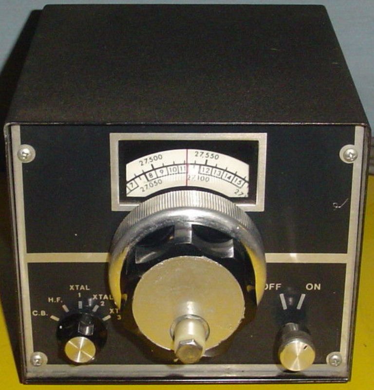
But the Siltronix VFO has many variants as I was to learn from google later on when contemplating using it on the TRAM. They made them to suit many CB Radios with different frequency outputs to operate the host radio correctly across 27 Mhz. Could I be that lucky mine was the right one to suit the Tram D201?? It did have a “3” in texta scrawled across the back but no official label designating it as a “Three” Model that put out 16 MHZ to suit the Tram D201. Well I checked it on my Frequency Counter after removing the inbuilt 110VAC transformer and replacing it with a 240VAC unit to allow pluging it into Aussie 240VAC supply so I would not have to use a stepdown transformer to 110VAC although I had a few around. Its just a much neater solution to plug into the home power points.
Well as you might guess the operating output frequency was not 16MHz but 9MHz!
DAMN! Thats a long way away!
So what to do…???
Although I get Adrian to do my radio repairs, I always try to do what I can to the best of my ability, but as Dirty Harry says “A man’s got to know his limitations”!
So I found out all I could about the VFO and the exact frequencies I needed to cover to operate the Tram over the correct part of the 27MHz spectrum the same as the onboard VFO to cover the forty channels. I knew I had to move the operating frequency about 7MHz and after some thought realised that there are two components of a oscillator circuit and the “Variable” of a VFO is the Capacitance so that left the inductance as the constant that needed to be changed up in frequency. So HOW..?? OK get an Inductor of some size to test the theory, ahh here’s a nice fat gold one about a 1/4 inch long and diameter in an old CB I cannibalise for parts, wonder if that will do it?
Now where the hell do I put it to get a frequency change of some sort? With power on to the VFO with the covers off, I identified the central Inductor spiral around a ceramic former about 3 inches high and 3/4 inch in diameter. On top there was a small variable capacitor for fine tuning the output with the covers on though a small hole.
Now many years ago I was in the business of repairing high & Low tech electronics equipment that was fairly unique in Australia that was made in the USA by Bell & Howell and others in the Micrographics industry. One thing I learnt in the RAAF prior to this was there is many times a low tech approach that can solve a high tech problem faster and easier! Not always, but enough to try first.
So picking the small gold copper inductor up with a non ferrous tuning tool I just tried poking it around with the bare ends of the inductor touching various parts of the Variable Tuning Capacitor and earth and the Inbuilt Inductor while watching the output of the VFO on my frequency counter to see what happened.
Lo and Behold! As they say. Well I found a few spots that changed the frequency output to around 100MHz!!
Sooo.. ok I need to move down the band a fair bit to the right spot at 16MHz. Realising that the Inductor I needed would have to be adjustable and much smaller and with finer wire for less inductance I looked again in the old mobile cb parts rig and spotted a likely looking variable inductor. Unsoldering it was a real pain, but I managed to extract it without destroying the fine wire former and adjustable permeable slug. OK, was all that trouble worth it I wondered as I dont have a good unsoldering station, just some solder wick and a weller soldering iron which is well past its prime back from my micrographics days 30 years ago.
Trying the smaller variable inductor with a tuning tool in the slug and touching the different four legs of the inductor to the similar spots I had previously where I got a 100 MHz I now got 17MHZ!!!! WOOHOO!
Needless to say, I had the VFO on the exact output frequency I needed for the TRAM in about two minutes of tuning the slug in the right spot about middway in the tube. The correct fixed location was soon soldered on the correct legs and secured in place in the VFO. With the covers back on the VFO I checked the output which had changed slightly, but was easily reset with the tuning cap though the hole.
“Arse Beats Class Every Day” was a Gunnie saying in the RAAF, and I have proved it many times.

More on implementation and improvements to this Tram D201 & VFO system soon….