

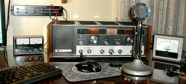
Bellhoppers Tram D201 CB Radio Base Station
As I have just got my Tram D201 back from my favourite cb radio tech, Adrian, I will start to write a lot more about this classic vintage “boat anchor” TRAM D201. He worked for the previous Tech’s Radio Repair company who had it for three years without touching it! He gave it to Adrian saying I wanted it fixed at no expense spared!!GASP!! Thankfully he did nothing to it! I managed to phone Adrian before he spent the equivalent of Boom Booms CB Radio Budget on it and he had already done a lot more than I though it needed but I trust him after 30 years. Serendipitous situation, thanks, the CB Radio Gods!
Until I actually put together a decent article soon, I will post the following information gleaned from many websites over three years ago when I originally had the Tram D201 shipped from the USA to Geelong Australia.
If you are the author of this information mainly from forums, I would be happy to hear from you so I can attribute the content to you and any website or forum you have. One of the reasons I reproduce this here is the annoying situation where you find great info on the web only to return to your bookmarked page later on to find the owner forgot to renew his domain or hosting or lost interest in the website and it is no longer there.
All my 20 + websites have been on continuously since begun, some since 1997!
A little about the Tram 201 and Tram 201A:
Both the Tram D201 and TRAM D201A base stations are one of the higher end AM and SSB CB radios ever made. At this era, the original 201 only came with 23 channels, however they were easily modified for extra channels. A few years later, the newer “A” version came out with a full 40 channels. Neither used an amplified mic, yet were one of the loudest base stations you can find.
For those that know a little bit about tubes and AM modulation, the TRAM D201A CB radio is famous for its high level Class C tube plate modulation. Class C biasing ensures loud AM modulation without distorting the audio. These radios also are very rare, so expect to pay more for a used TRAM D201A radio is good condition. Believe or not, the matching D104s for Tram D201s and D201a were not amplified microphones, yet these radios have loud audio. They were built to amplify the audio from within.
If you’ve been in the hobby for awhile, you’ll remember how loud these base stations were, and how neat it was experimenting with the older tube type and nice sounding base units, such as the TRAM D201A base cb radio.
Not sure who is the lucky owner of this nice and tidy Tram D201.
Gotta say I love my Tram D-201 VOX radio. As far as an out of the box radio goes, this was the best sounding CB rig ever produced. Plate modulated audio from a 25 watt 6L6GC sure had Browning stumbleing to acheive the same audio and power output. The Tram still sounds good with the smaller of the two wire wound voltage dropping resistors shorted. Will key about 10 watts then with lots of PEP.
Thanks to Svetlana, the problems of locating a quality 6L6GC are over. Check out the SV6L6GC. The tube is about $35 and has been designed to be a winner. Heavy mica insulators, gold grid wires, and heavily coated oxide cathode really gives some stiff competition to the old RCA.
#10
Shockwave, Oct 12, 2009
Frequency range and power out would also depend upon mods that have been done to the radio.
Its been a number of years since I had a D201A, from memory transmit on the variable was up around 27.8-9ish, and a few below 1. the D201, I believe is about 27.6 and a few below 1. The 201 I have here has also had the common -1 mod done and with the flip of a switch goes down around 26.3 or so.
As for Power out, a good working 201 with good tubes could be made to easily run about 12 watts carrier, maybe 30-35 PEP. also another common mod which involved jumping some large power resistors to increase voltage. Many mods to the radios over the years, some even put 6146 in for the PA.
I would suggest forgetting about “Strapping” the power resistors, and leave it at stock voltage, leave the 6L6 coast along at the factory original output level which yielded 3-8 watts or so. My reason for suggesting this is the cost and difficulty in obtaining suitable 6L6 tubes. Which are in big demand by the audio guys Good RCA 6L6 tubes will easily bring $50 each, and they won’t get any cheaper….
#6 Last edited: Oct 1, 2009
MisterFatty, Oct 1, 2009
packrat
I would have to agree with leaving the radios output stock. They are getting older, and the parts were marginal when new, and will be strained by modification. Extra heat means extra problems. Besides, they are one of the best sounding radios to begin with, so why not just enjoy a Tram as it was meant to be.(y)
#7
packrat, Oct 1, 2009
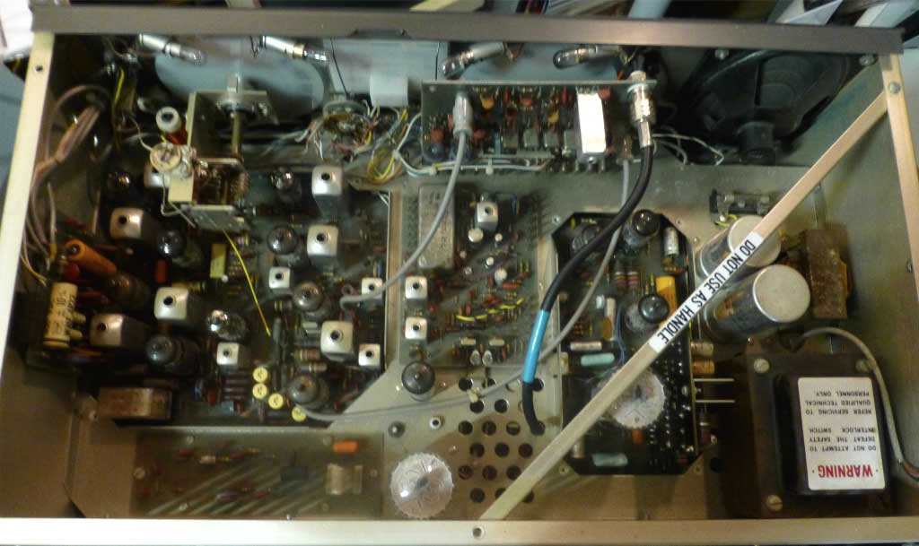 This is the insides of my (admin) Tram D201, which is not too bad for a radio built in 1975 and has exposed valves generating a lot of heat over that time.
HiDef
Plan to change out some of the resistors on the printed circuit board models. They drift high and make the receive deaf.
The world is full of cheap 6L6s. There are certain suffix 6L6s which are sought after by audio pholks. You won’t need those types. That radio does indeed make a nice 12 watts and about 50 P.E.P. with one of those wirewounds jumpered. It can make 30 watts carrier if more are hacked across but the modulator does not keep up.
I put a pre-war 6L6 in mine just to be on the air with a 70 year old tube.
Any power mods need to be followed by adjustment of the AM audio compressor to keep negative modulation below 100%. The compressor circuit is very good. Find a good D-104 cartridge for best transmit audio. No preamp is needed. That will actually make the tone worse.
Noise blanker is pretty good.
Widebanding the thing will probably show up the usual CB radio bandwidth fall off problems. I have one on 10 meters and it works well across 300 khz then Po and receive start to roll off.
A rough estimate of the use of these rigs is to look at paint discoloration on the underside of the lid. The tOOb’s heat gets to the paint.
Best of luck.
#8
HiDef, Oct 1, 2009
Any power mods are almost guaranteed to cause trouble. Circuit board damage is almost guaranteed, and power supply problems are probable. Lots of these great radios died at the hands of uninformed modders. Look at all of the trams being sold on ebay with problems.Remember, these radios are getting pretty old, and were built with parts that were just able to do the job, and not much more. They work great as designed, so why do more that a good tune up?:confused:
PR
#11
packrat, Oct 12, 2009
Any power mods are almost guaranteed to cause trouble. Circuit board damage is almost guaranteed, and power supply problems are probable. Lots of these great radios died at the hands of uninformed modders. Look at all of the trams being sold on ebay with problems.Remember, these radios are getting pretty old, and were built with parts that were just able to do the job, and not much more. They work great as designed, so why do more that a good tune up?:confused:
PR
Packrat makes a valid point however it only applies to the D-201A made in Mexico. Just before Tram went out of business they tried to cut costs. The core on the power transformer used in the last radios made was 33% smaller in size and 33% less powerful. Evidence of this is found by looking at the power output stages of late model radios. The final tube was stepped down to a 6DG6 and a 10 ohm resistor was added at the final tube socket to reduce output.
This is certainly not the case with the older D-201. The radio was a powerhouse with a 6L6 modulating another 6L6 and a power supply with plenty of headroom. These tubes are about four times higher plate dissipation then the 6AQ5 or 6BQ5 used in any other CB output stages. With this in mind I have to disagree with this radio being built without extra headroom.
Most failures in the D-201 are related to the old carbon resistors changing value, filter caps drying out, and tubes gone bad. All of these problems can be greatly reduced by installing a small fan on the back of the rig. I can’t count how many Trams I’ve seen over the years with open resistors in the B+ line feeding the SSB IF RX tubes. I can count how many I’ve seen with a blown power transformer. It was a single D-201A in decades, made in Mexico.
I suppose it really comes down to what you are doing with the radio as to if you should mod it to do more power. For example if you’re driving an amp, 2 or 3 watts either way could make a huge difference in output, while being barefoot this power change means almost nothing. An old Tram with the full sized power transformer can easily make twice the rated carrier and still 100%modulate it without stress.
#12
Shockwave, Oct 12, 2009
HiDef
Jumping the wirewound resistor to make the radio do 12 watts makes zero change in the power transformer’s load. The transformer delivers power to which is wasted as heat in the resistor or extra DC power input power to the final when jumpered.
If your D201 can’t fully and cleanly modulate 12 watts of AM/50 watts P.E.P. (with the resistor jumpered) it’s sickly and needs attention.
#13
HiDef, Oct 12, 2009
MisterFatty
HiDef said: ↑
If your D201 can’t fully and cleanly modulate 12 watts of AM/50 watts P.E.P. (with the resistor jumpered) it’s sickly and needs attention.
let me make this a bit clearer, and this IS from experience, and was noted on BRAND NEW, fresh out of the box 201 radios.
Increasing output power beyond 7-8 watts carrier WILL make a noticable difference in transmitted modulation. Will the Tram 100% modulate A 12 watt carrier, yes it will, will there be a notable difference in transmitted audio between a 5 or 6 watt carrier, and a 12 watt carrier, YES there will be. Will this difference be recognizable by an average CB’er probably not.
#14
MisterFatty, Oct 12, 2009
Shockwave
Shockwave
Sr. Member
I LOVE IT!
Joined:Sep 19, 2009
Messages:2,522
Likes Received:726
I think what some people miss here is that these resistors are not just voltage dropping resistors. They are part of the Heising modulation circuit used in the radio. These resistors have an electrolytic cap across them for a reason. The resistors reduce DC power to the tube while the cap allows the AF modulation power to pass through without reduction. The overall effect is reduced carrier and increased modulation.
There is obviously going to be a balance here between the maximum carrier that can be produced while still being able to fully modulate it. As mentioned this limit is around 8 watts carrier. That’s why you should only bypass the smaller 1.5 K ohm 10 watt resistor if you need more power and not the 2.7 K 15 watt.
A previous post suggested that this will not place more load on the power supply since we are no longer wasting power as heat in the resistor. This is not exactly correct. You will place about 20% more load on the plate supply because without the resistor there is more current flowing. Less resistance means more current. Voltage divided by resistance will tell you that.
Some may find this hard to believe but I once modified a D-201 for a customer that produced a 35 watt carrier with 140 watts PEP! The final stage was still class C and plate modulated. I replaced the AF and RF tubes with 6146B’s and replaced the power transformer with one that made 600 volts DC.
I regulated the screen voltage on both tubes with OA2 voltage regulators, used a zener for cathode bias on the modulator and replaced the modulation transformer. Added an adjustable voltage regulator for the solid state pre driver so that the radio could have variable power too.
One thing I did overlook was the mode switch could not handle the extra B+ voltage across it’s contacts and flashed over on the first transmission! I replaced the damaged wafer in the switch and rewired it so a relay would switch between modulated B+ on AM and pure DC on SSB.
This modification is very labor intensive and took over 40 hours of bench time. The only reason I did it was because the customer said “money is no object if you can accomplish what I want! A thousand dollars later and one week in time produced exactly what he wanted 10 years ago. The radio is still working great today with no service time at all.
#15
Shockwave, Oct 12, 2009
Posted on Friday, June 20, 2003 – 9:03 pm: )
i just bought a D201 and i have a question…i pluged it in and it has no recieve…i tested all the tubes they are all good…i dont have a mic for it yet..does the mic need to be pluged into the radio to recieve like other radios i have had before…and does anyone know were to turn up the recieve inside the radio
2600
Posted on Saturday, June 21, 2003 – 12:24 am:
No, the mike is not needed to receive on this radio. I DO hope that it’s a 23-channel D201 and not the 40-channel D201A. The channel switch used in all but a few 201A radios is a complete disaster, and wears out in a very decisive way after very little use. Most of the “mint” 40-channel Tram radios you see were put up on the shelf before a full year of wear-and-tear could occur. The channel selector would fail, the factory closed, warranties expired and the radios went onto a shelf with little use on them. The average price to fix the 40-channel switch was $175 twenty years ago, and has only gotten more expensive since then.
You did not mention if the S-meter shows any activity when you change channels. If the S-meter is laying dead, and doesn’t flick around from channel chatter, you will probably find more than just one problem with the receiver section. It’s a little like finding a 1974 Olds 442 under a tarp with 5000 original miles, but with NO service done to it since 1974. You can’t just jump into it and drive to California. There WILL be maintenance issues, plenty of them. It’s not JUST the miles, it’s the years, too. There won’t be JUST an adjustment screw or two that will get that Olds to California.
Any serious effort to put a D201 on the air for regular use will call for a “100,000-mile tuneup” even if it has very few actual ‘miles’ on it. Since all the two dozen or so electrolytic capacitors are on borrowed time after 25 years, a “scorched earth” procedure to replace every one of them is just ths start. The D201 radios have some heat issues with the wattage rating on about a dozen power resistors inside. Makes the color bands fade and bubbles to form on the surface. When that happens, the electrical quality of that part fades with the color bands. Most of those dozen resistors get replaced with larger ones that will run cooler, and longer. Leaving the old ones in can wear out tubes prematurely, or just prevent it from performing.
The relay is rare and expensive. It can make any part of the radio drop out when it goes bad. Crystals can fail from age alone after 25 years. Tube sockets (in the circuit-board versions) get loose with heat exposure. The rotary switches use silver-plated contacts. A long period of storage can allow black tarnish to build up on switch contacts and make any part of the receiver (or several parts) roll over and play dead.
On a more positive note, the original owner’s manual had a section on troubleshooting that wasn’t half bad. It did assume that a WORKING radio had just started to act wrong, and would suggest what to try first. A radio that may have six or ten separate problems is a whole different kind of troubleshooting.
As far as the idea of ‘turning up’ the receiver? There are about twenty adjustments in the radio that affect the receiver. Some of those also affect the transmitter performance. This doesn’t include the trimmer caps that set the channel crystals on frequency. Turning up the receiver means getting all of those adjustments peaked correctly.
BTW, the preferred mike to use on this radio is a STRAIGHT unamplified D-104. The amplified D104 will do okay, but has to be turned ‘wayyyy down, and won’t sound as good when you talk up close to it. That’s what the factory packed in the shipping carton with a new radio: a straight D-104. Just make sure the pickup element (cartridge) in the mike head is not old and weak. They tend to get that way around 20 years, even if stored in a cool, dry place, sooner in humid surroundings.
And then again, maybe a good, hard whack to the right side of the cabinet ?……..
73
Tech808
Posted on Saturday, June 21, 2003 – 10:12 am:
Clark514,
As 2600 said it can be a major time consuming effort, to figure everything out on a Tram, but when working right, they are a fair to good radio.
If you have a D201A you might check to see if it has the Stock BA Board in it, if not then you want to get one of the New BA Boards. Also if you look inside and do not see a bunch of NEW resistors (Not the old brown ones) raised up farther off the board than others, then this also MUST be done.
“HEAT” inside is the MAJOR problem with the Tram’s
DO NOT ADD A FAN INSIDE or you will find your frequencies will drift everywhere. They need to run hot.
If you were lucky to get the Owners manual with it that is a big help.
Without a TRAM BOARD TESTER or access to one, you can go on forever trying to figure it out.
Should you want the mods/upgrades & repair info send me an e-mail with your mailing address.
In the central US, Maycom still has a board tester and on the west cost there is Gary who was one of the original Tram Techs and now has all the publishing rights to the Tram & Browning Books / Manuals & Material. He is is CA.
To get one put in Very good Running Condition is Expensive.
I just spent three months on one a friend in GA bought from eBay, It appeared to be like NEW Condition.
With tubes, upgrades, replacement parts, resistors, replacing dried out cans, New BA board, Fixing Main Board, Channel Mod, High Power mod (15 watts), switches, time invested, and adding Digital Freq Counter to read the channels, run him well over $600.00. Not counting the $400.00 plus he paid for it.
But, he always wanted one so he was happy.
The Tram’s 201 & 201A was my favorite’s back in the 70’s and I sold probably 100 or more of them.
If you hear one on Skip you can tell, as it will be the loudest thing out there, but now you can buy a 2995DX cheaper than the repairs on one to get it running right.
And Tubes! Yes you can still order New tubes but! Remember they are NOS (New Old Stock)
The Trams & Brownings were good radios in their time, but now you better have a Big/Deep wallet for labor / testing and repairs. And hopefully someone who knows what they are doing when working on one.
The sad thing is if you put major bucks into it to get it right you may never re-coup your investment, if you ever decide sell it. It has to be something you want to keep and use.
Just my thought’s
Lon
Tech808
Clark514
Posted on Saturday, June 21, 2003 – 6:28 pm:
thanks to all you guys for all the sugestions. And yes it is a D201 not a D201A. i got it cheap. So i am willing to put money into it because i plan on keeping it a long time because i have always wanted one. I had a browning years ago and i am sorry i ever got rid of it. It was a Mint Mark 2, boy did that radio scream…..Talked to Alaska and Japan on that radio. So since i posted this problem i have opened the radio and…….it looks to me the BA board needs replacing…so i have ordered one should be here in a week. also i found some cold soder joints…..boy are you guys right the circut board has gotten brown in some areas…radio has had some work done to it over the years i can see some resistors have been changed and sone caps too.
2600
Posted on Monday, June 23, 2003 – 12:09 am:
Good. It’s a 23 channel. A low-miles 23-channel is much harder to come by. They just didn’t “die young” like the 40’s did. Wear and tear take their toll. If the thing looks at all cruddy, removing the tubes and washing them in ammonia-base window cleaner, or such will remove whatever “insulation” is stuck to the outside of the glass, AND will shine up the metal surfaces of the pins. Rinse them in water. Be sure to dry them thoroughly before powering up. This is better done one at at a time. There are five 6GH8A tubes and three 6BA6 tubes in the radio. If you don’t return the same tube to the same socket it came from, that could affect the alignment. That’s one of the main reasons those “peaking” adjustments are there. The manufacturing tolerances from one tube manufacturer to the next will affect just where the “peak” will occur on those tuneable slugs. Scrambling the tubes around can change the calibration of the Manual tuning dial, the S-meter zero setting, and receiver sensitivity.
Tubes that make scratchy noises when tapped may have tarnished or loose pins in the tube socket. A NON-RESIDUE contact cleaner is worth trying, if the socket still grips the tube pins. If the socket feels loose, squeezing them back together with a pointy tool to tighten them is only a temporary fix. After thousands of heat/cool cycles, the metal in those socket pins loses its spring temper. When that happens, the socket just has to go. A radio that was run 24/7 will get hot enough to make the black plastic tube socket insulator crumble and crack.
Note that there is only ONE version of the BA board to match a 23-channel radio. The 40-channel was made with TWO different, non-compatible versions. A mismatch of the wrong BA board/radio can either cripple the audio power, or cherry the audio tube the moment it warms up, popping a variety of parts before it cracks the glass and kills the main AC fuse. If you are offered a 23-channel Tram D201, and the BA board has jumper wires where the left-side resistors fuse/capacitor belong, DO NOT power it up. A 40-channel D201A MIGHT well be built to take that board, and will have an unmarked trimpot on the SOLDER side of the main AUDIO board if it was. The BA board with the jumper wires will SMOKE a stock, unmodified 23-channel D201. Guaranteed.
The soldering on both sets of “auxiliary” board pins, under each main board bears checking closely. For whatever reason, the factory soldering would go bad on both sets of these pins, underneath each main circuit board. Resoldering with a good-quality rosin-core solder will usually do the trick, unless heat has begun to lift the foil traces.
One last thought. Does the guy with the new BA board (uh, TramDoctor?) also supply new PINS to go on the main board, and plug onto? If not, they are worth getting. The round pins that Tram used for the BA board have a wear problem. The plating on the round pins will just scratch off, eventually. Square pins can be had that will hold up better. Besides, they have bright, new shiny plating on them. If a NEW BA board has ‘scratchy’ noise problems when jostled, those old, round pins may be worn. If someone tried to SCRAPE those pins clean with a knife blade or abrasive, the solid-pin metal exposed by removing the electroplate will get tarnished and noisy only a few days after cleaning with solvent.
Have fun. Sounds like it will be a LOT of fun.
73
Top of pagePrevious messageNext messageBottom of page Link to this message
frasiercrane
Posted on Thursday, July 17, 2003 – 1:28 am: Edit Post Delete Post Move Post (Moderator/Admin Only)
ah.. if I had $75 for every Tram I refurbed.. oh wait.. I did have $75 for ever Tram I refurbed…
Anyway.. been a long time.. but what I do remember is I used to replace some of those resistors on that little plug in board with those 4 watt rectangular ceramic deals… worked rather well.. make a little ‘u’ bend in the lead about a quarter inch from the resistor so that they sit up off the board a bit.
Also, I can’t say I ever saw one where I could adjust all of the crystals on freq… a few years in that heat would do them in pretty good.. I toyed with the idea of making a PLL board to go in them.. easiest solution was to just use the VFO and forget the channel selector.
Tram D201
Tweaks and Peaks
Modulation: Adjust R647
AM Power: Adjust C711,C712
ALC: Adjust R719VFO Transmit Mod
1) Remove Orange wire from relay and connect to PC board Ground
2) Install jumper from White/Blue wire on relay to White/Orange wire on relay
3) Remove White/Red wire from
D-125, Remove Anode end(no stripe) of D-126 from front wafer switch and connect to White/Red wire that was removed from D-1254) The channel selector must be on channel 9 when using the VFO. The clarifier will only change the XMIT frequency when in MANUAL position.
Check the BA board reall close. A lot of problems start there. Those caps get a lot of heat on them. Many folks change the resistor to cement type 5 watt. These should be carbon film or metal Ox. resistors. Wire rounds do not work well in this circuit and could possibly contribute to squeals and hows in the RX. The pins coming up from the board also come loose with vibration since there is nothing holding the board up but the pins.
At the base of the audio tube towards the back is a 2 watt resistor. Can not remember the value. But it goes bad quite often in these older rigs. I have seen this changed out in many units to the wrong value.
Also check the 10uf X 4 X 450 cap real good on each leg.