January 2016 – by AX05
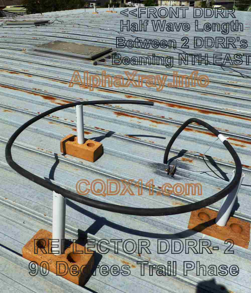
DUAL DDRR C0-Phased CB Antenna Array for 27 MHz Citizens Band Radio
DDRR is an acronym for Directional Discontinuity Ring Radiator, an OMNIDIRECTIONAL, VERTICALLY Polarised Radio Ariel for Transmission and Reception of HF signals.
I have decided to test the ‘Barracuda Base’ DDRR CB aray with adding another CB band tuned DDRR antenna I had setup on the garage that seemed to work well on my Tram D201 valve CB radio for DX.
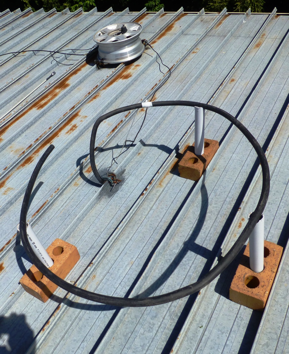
So I unconnected the Quarter wave 9′ whip and replaced it with the other CB DDRR as shown below. More on DDRR + 9′ Whip HERE 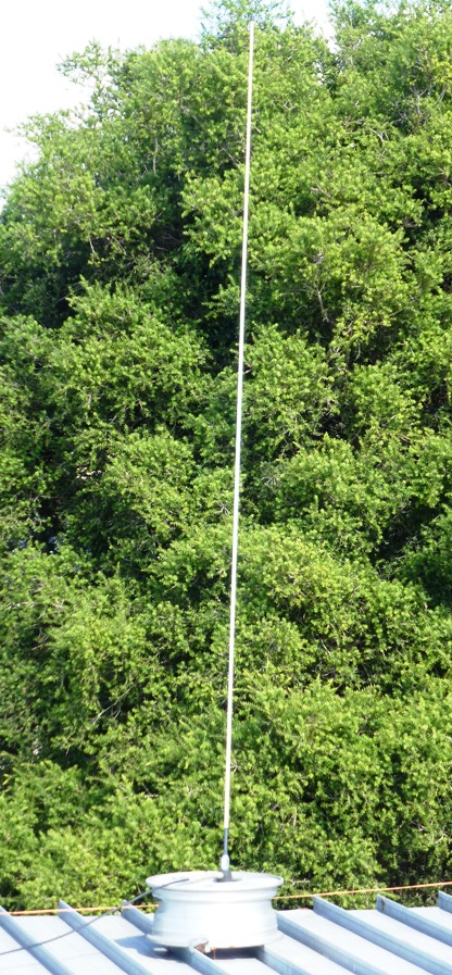
(before I fitted the cable ties to anchor the 20mm insulated copper stranded main element to the plastic tube uprights)
This made my wife very happy to see I had removed the last offensive to her eyes antenna from the roof!! You cant spot a 12″ high DDRR!!
The construction of the main radiator element is a rubber insulated electrical cable of 20mm diameter of stranded 3mm copper wire which is extremely heavy( but probably irrelevant.)
I am sure if you used RG213 or Heiliax or anything approx that diameter it would work just as well as mine as long as you follow the basic rules I did or more to the point experimented with to arrive at!
I started with cutting the long length of cable I had to a 1/4 wave or 104 ” on 27 MHz CB Band.
Then I measured 12″ ( which is a harmonic of 27Mhz) and Bent it in a vice with a hammer to 90 deg. after cutting a 4″ piece of rubber to bare the copper wires. This is where it is clamped to the metal roof securely.
Then you just bend it side ways into a loop so the end comes around to within 8″ of the upright. This distance is reasonably critical around 8-9″. Surprisingly the tapping point on the cable for the centre coax conductor seems to be around 8-9″ from the upright on the other side of the main element. See the image if this is not clear. I just hammered a nail into the cable every cm for 10cm each side of the 8″ point and tried every one with the Sark M100 antenna analyser until I found where it was resonant around 27.205.
Then I moved the earthing point of the coax lead around the bottom of the main conductor to tune it even closer to 50 Ohms. After a lot of trial and error it seems on my system the earth point needs to be the grounding point of the main radiator to the roof so that is where I clamped it.
Removed all the extraneous nails and securely connected the centre of the coax lead to the one that tuned in the best on the Sark Analyser, rechecked and had 53 Ohms which gives a SWR across the CB Band which is acceptable at less than 1.2:1
The DDRR CB Ariel looks like a piece of rubbish and it is, it just does not perform like it looks. It performs EXCELLENTLY!!
Mainly the LOW NOISE makes it a joy to use, the gain and performance of a single DDRR compares to a 9′ whip as it is mainly vertically polarised radiation even though it lies flat.
I have taken a highly technical construction with a lot of math behind it and extrapolated it to a basic laymans construction that has proved to work for me and it can for you as well.
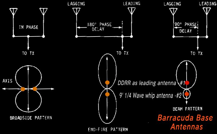
I jumped up 4 S points to 69 Darrens station in Geelong just by doing this so the beam pattern obviously changed a lot from where it was going before. Everyone in Geelong about 30 KLms to the west reported the same. I need to work out the actual beam width and directions soon so have the idea to lock my mic to TX on AM on an unused chanel mid band on a watt or so. Then setup the laptop in the car with the SDR going with a small 27Mhz antenna attached and drive around in a half kilometre perimeter to take signal strength readings to plot on a google map.
This would let me know where the beam is going and relative strength to allow better alignment of the antennas. I have the roof space to move them around to get the best direction I want to go.
My antenna is based on the extremely technical invention of Dr. Boyer, but dumbed down to the minimum construction work for the maximum CB operation on 27 Megahertz Band.
One day I will make one to the exact specs of Dr. Boyer and compare the correctly constructed DDRR antenna to my thrown together heap of resonant DDRR rubbish!
The DDRR (Direct driven ring radiator) was invented by Dr. Boyer from Northrop, for military applications in the 50s.
It stayed classified until Dr Boyer published an article titled “Hula hoops antennas” in Electronics (Jan 11, 1963). “73 Magazine” published also a two part article from Dr. Boyer titled “Surprising Miniature low band antenna”. The article is quite technical and contains a very precise mathematical formulation of the DDRR based on transmission line theory.
In layman’s terms a DDRR is just a short vertical monopole (vertical post) attached to a transmission line tuned by a reactance (ring plus vacuum capacitor). The reactance of the capacitor is transformed by the transmission line and will under specific conditions (length, value of the capacitor, etc.) make the vertical post resonant. Slight variations of the capacitor will lengthen or make the transmission line “shorter” and allow tuning of the antenna on a certain range.
First lets make a difference between the DDRRs patented by Dr Boyer and the ones that we can find here and there in amateur publications.
Boyer designed two basic models: the one ring DDRR and the two rings DDRR. More HERE http://www.orionmicro.com/ant/ddrr/ddrr1.htm