
COBRA RADIOS & MODIFICATIONS

This page is for informational/educational use only and comprised of archival URL information with back links.
NEW INFORMATION ON THE COBRA 148 NW ST.
Cobra has really shot themselves in the foot with this new radio, why you ask? I’m getting to that but first let me say that Cobra has been the industry leader in producing good quality CB radio’s down through the years, there was the great line of Mobil “AM” radios such as the 25LTD, 29LTD. Their Sideband radios such as the 146, 148 gtl and 2000 were superb, they were stable and a radio you could be proud of.
The first thing that happened to Cobra was that Uniden wanted to raise the price on there PC boards, Cobra did not like this so they got some other company to make there boards cheeper! The first thing that happened was that they started using 1/6 Th. watt resistors throughout the whole radio, don’t know how many radios failed in the field because of this, I had several myself that had a failure of several resistors that had previously been 1/2 watt. Of course this is all history, they fixed that problem.
Now we have this new radio, the 148 NW ST, It looks real pretty at night. I had a customer send me a 148 NW ST for peaking and tuning for better receive and transmit. So before doing anything else, I hooked it up to my antenna to get some radio checks, well, AM was OK, nothing to write hone about but clear and clean. Then I went to Sideband, now people say they can’t “clarify” me in, What! So I tried some others on the band with the same results, can’t clarify me! So I’m thinking maybe my oscillators are off frequency so I check them and find that they are a little off so I align them. This time is the same as the last, they can’t clarify me!
So I really got concerned! After checking the oscilator frequencies I find that they change when I modulate! What the Hell! they are not supposed to change, they are supposed to be rock solid! I placed a volt meter on several test points and found that the voltage to the oscillators is changing with modulation! So I start looking for the reason for this and ran into the cause right away.
The new units don’t have the MB3756 Voltage Regulator, They have decided to further cheapen the radio by doing away with it! and installed a 3 pin voltage regulator in its place with a series resistor on the 8 volt pin, on the input pin there is no voltage drop, on the output pin there is.
What this all boils down to is this, the radio is in my opinion now is somwhat “unstable” on sideband and I for one, would not own one!
To my knowledge it could be inproved with some additional filtering and RF bypassing.
Handheld CB Radios
Cobra HH28 Basic low-priced 40 channel CB
Cobra HH33 this model is discontinued!
Cobra HH34 Basic handheld with charging jack and lighter plug.
Cobra HH36 ST this model is (Discontinued)
Cobra HH37 ST 40 chan. with Soundtracker and charging jack
Cobra HH38 ST This compact model includes 10 weather channels Soundtracker and charging jack
Cobra HH45WXST this model is discontinued! (refurbs may be available)
Mobile CB Radios
Cobra 18WXST CB Weatherband Radio
Cobra 19 Ultra 2 Compact Mobile CB Radio
Cobra 25ST (Discontinued) Classic CB Radio With SoundTracker.
**NEW** Cobra 25 NW ST CB Radio With SoundTracker and backlite front panel!
Cobra 25STWX Classic CB Weather Radio With SoundTracker
Cobra 29ST Classic CB Radio with SoundTracker
Cobra 29LTD ST Night Hawk (Discontinued) Classic CB Radio with SoundTracker and backlit controls.
**NEW** Cobra 29 NW ST Deluxe AM CB Radio With SoundTracker and backlit front panel
Cobra 29STWX Classic CB Weather Radio With SoundTracker
Cobra 75WXST Compact/Remote Mount CB Radio With SoundTracker
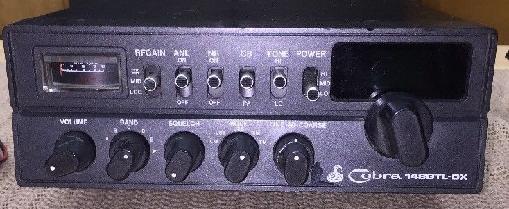
Cobra 148GTL ST (Discontinued) SSB Mobile with SoundTracker technology.
**NEW** Cobra 148 NW ST Top-of-the-line CB Radio With SoundTracker and backlit front panel
Cobra 148F (Discontinued) Cobra’s top-of-the-line SSB Mobile with Frequency Counter.
Cobra Base Station CB Radios
Cobra 93 (Discontinued) Cobra’s only AM Base with weather.
Cobra 2010 (Discontinued) The Cobra 2010 is Cobra’s newest and best base station ever!
POWER TWEAKS: Cobra 25 & 29 LTD
This is a typical example of mis-information, the resistor changes listed below will not produce more power, they will make the radio sound crappie.
1. Change R76 (3.3k) to a 1k (near the mike socket) <-NOT OK AS IT MAKES THE MIC PICKUP TOO MUCH BACKGROUND NOISE.
THE ABOVE WILL PRODUCE DISTORTION AND
MAKE THE MIC CIRCUIT HARD TO CONTROL.
2. Change R43 (10 Ohm) to a 2.7 Ohm. <-NOT OK
3. Change R108 (1 Ohm) to a .47 Ohm. <-NOT OK
BOTH OF THESE CHANGES WILL PRODUCE OVERDRIVE
IN THE PRE-DRIVER AND DRIVER STAGES, NOT GOOD!
4. Replace stock final with a 2SC1969 transistor. <- THIS IS OK TO DO
5. Re-tune coils L10,L9,L8 for maximum forward Power.<- THIS IS OK TO DO
Select Cobra Power Mods
————————————-
2000 GTL,2010
Cut R-131 Tune L47, L48, L46, L45 and L38 for max RF output
AM Carrier Power VR10
Mod Meter VR7
AM Signal meter VR1
—————————————–
142GTL
Lift the Emiter leg of TR32, and insert a 1K resistor from the leg to ground. Adjust L36,L37 for max RF output
AM Power VR6
SSB Power VR7
VR1 “S”Meter
VR2 Squelch
VR3 TX Freq
VR12 Mod Meter
VR10 TX Power Meter
—————————————–
148GTL+F
Lift the Emiter leg of TR24 and insert a 1K in series with it, to ground.
——————————————–
29GTL/LTD/CLASSIC
Just turn up VR-4 for Max modulation, Adjust L17, L20, L21, L16 and L14 for max RF output.
Modification: Change stock final to a 2SC1969 Change C71 to a 33uf 16volt polarized electrolytic capacitor.
VR1 receive gain
VR2 receive signal meter
VR3 squelch
VR4 AMC
VR5 transmit power meter
VR6 antenna warning light
————————————————–
25GTL/LTD/CLASSIC
Just turn VR-5 for Max modulation, Adjust L10, L9 and L8 for max RF output. Modification: Change stock final to a 2SC1969 Adjust L10,L9,L8 again Change C91 to a 33uf 16volt polarized electrolytic capacitor.
————————————
Cobra 18RV 23 Plus
Retune L305, L306
———————————–
Cobra 90LTD
Cut D203, Retune L304, L305 and L306
———————————–
Receive Boost Cobra 29
One, Locate pin 14 of the PLL chip, and the Positive (+) side of C-12.
Two, Install a 220k ohm pot between these two points. The smaller the value, the more the receive is boosted.
NOTE: adjust this pot with care as too much gain will SLAM your “S” meter, (This works! I’ve tried it, Peg Leg)
———————————-
Cobra 2000
No Audio on AM Transmit with good Carrier, This problem is more common in the “older” 2000’s but is relatively easy to fix. Look for the collector of TR-23, you should read about 4.5 V with a dead key. If you find that this voltage is not present, check on the opposite side of R-120 for 6.5V. Most likely this voltage will not be present; if this is the case, C18 has shorted and needs to be replaced. This is a 330uf, 10V electrolytic capacitor beside L31. To prevent “future” problems, replace with a 16V unit.
COBRA 29LTD RECEIVE PROBLEM ( unit with – 1/6th. – watt resistors )Problem :
Receive Audio Low.
Transmit Audio normal.
100 uV signal input did not move meter much. (should indicate S-9 on the meter)
Noise Blanker Didn’t work.
Found problem: R-31 is supposed to be a 47k 1/6W and it opened up to 137.5k
NOTE : The new units have 1/6W resistors, the quality control is not good, this is the second example I’ve seen of this. The newer units may have corrected this problem.
Cobra 148 GTL
SYNTHESIZER ALIGNMENT
———————————————
Input of Freq. Counter To TP-13 (IC-1 Pin 8)
CH-19 ——————————– Check for 10.240Mhz.
———————————————————-
Input of Scope To TP-10
CH-19 AM —— Adjust L-21 for Maximum RF (3-4vPP Typical).
———————————————————-
Input of DC Meter To TP-9
CH-40 AM
Adjust L-19 for 3.2 Volts DC – 2.2 Volts DC on CH-1
———————————————————–
Input of Scope To TP-1
CH-19 AM ——– Adjust L-20 for Max RF (190 MvPP Typical).
———————————————————–
Input of Frequency Counter To TP-1
CH-1 AM ———– Adjust L-23 for 34.7650 Mhz. +/- 20 Hz.
CH-1 USB ———- Adjust L-59 for 34.7665 Mhz. +/- 20 Hz.
CH-1 LSB ———- Adjust L-22 for 34.7635 Mhz. +/- 20 Hz.
———————————————————–
Input of Frequency Counter To TP-10
CH-1 AM ——————————– Check for .790Mhz.
———————————————————–
Input of Frequency Counter To TP-3
CH-19 USB ——- Adjust CT-2 for 7.8015 Mhz. +5 Hz. -0 Hz.
CH-19 LSB ——- Adjust L-30 for 7.7985 Mhz. +0 Hz. -5 Hz.
CH-19 AM XMT
Disconnect TP-7, TP-8 Adjust L-31 for 7.8000 Mhz. +/- 5 Hz.
———————————————————–
Input of Frequency Counter To TP-15 (FET-1 Gate 1)
CH-19 AM —————————– Check for 7.3450Mhz.
———————————————————–
Input of Frequency Counter To Antenna Input
CH-1 AM ———————— Adjust VR-5 for 26.965Mhz.
———————————————————–
RECEIVER ALIGNMENT
Set output of Sig Generator to 27.186 Mhz.
Ch. 19, USB ——- Adjust L-14, L-12, L-10, L-9, L-8 and L-7 for Max. output at speaker
———————————————————–
Set output of Sig Generator to 27.185 Mhz.
Ch. 19, AM – Adjust L-15, L-13 and L-3 for Max output.
————————————————————
Set output of Sig Generator to 27.185 Mhz.
Ch. 19, AM – Adjust L-6, L-5 and L-4 for Max output at speaker.
———————————————————–
NOISE BLANKER ALIGNMENT
Set output of signal generator to 27.185 AM, 1000 Hz. @ 30%
modulation. Input of O-Scope to TP-17, (D-2 Cathode) Inject a 100pps,
1uSec. pulse width signal at antenna input.
Switch noise blanker ON
Adjust – L-1 and L-2 for a Maximum while maintaining wave form Symmetry
———————————————————–
RECEIVER ADJUSTMENTS
Set output of signal generator to 27.185 AM, 1000 Hz. @ 30% modulation. Output level 1000 uV. Set Squelch Maximum.
Adjust VR-3 so that squelch just breaks.
———————————————————–
Set output of signal generator to 27.185 AM, 1000 Hz. @ 30% modulation. Output level 100 uV.
Adjust VR-1 for s9 on signal meter.
———————————————————–
Set output of signal generator to 27.186 USB, 1000 Hz. @ 30% modulation. Output level 100 uV.
Adjust VR-2 for s9 on signal meter.
———————————————————–
TRANSMITTER ALIGNMENT
Input of RF wattmeter to antenna input
Ch. 19 AM Adjust L-47, L-48, L-46, L-45 and L-38 for maximum output
NOTE: Do not touch L-36 (TVI filter), factory adjustment is O.K.
———————————————————–
TRANSMITTER ADJUSTMENTS
Input of RF wattmeter to antenna input, no Modulation.
Ch. 19 USB, Dynamike MINIMUM
Adjust VR-4 for MINIMUM RF output.
———————————————————–
Input of RF wattmeter to antenna input, no Modulation.
Ch. 19 USB, Dynamike MINIMUM
Insert a DC AMP meter at TP-8 (Violet wire) Adjust VR-9 for 25 mA.
Insert a DC AMP meter at TP-7 (Green wire) Adjust VR-8 for 50 mA.
———————————————————-
Input of RF wattmeter to antenna input, Inject a two-tone 500 mV signal at mic input,Dynamike MAXIMUM Ch. 19 USB
Adjust VR-11 for 11.0 watts PEP RF output maximum.
———————————————————–
Input of RF wattmeter to antenna input
Ch. 19 AM, Dynamike MAXIMUM
Adjust VR-10 (AM carrier) to 3-4 watts RF output
———————————————————–
Input of RF wattmeter to antenna input
Ch. 19 AM
Adjust VR-6 So that it agrees with your output meter.
REPAIR TIPS: 29 GTL:
1. “Motorboating”: Locate C242(.001)on pin 5 of TA7222 audio ic and move to pin 4 of ic.
2. Receive on adjacent channel: Bad solder joint to C131 (next to 10.240 crystal).
29 LTD:
1. OVERMOD: Check D11
2. PLL dead, no TX or RX: Shorted C112
3. No TX/RX with Channel LED lit on RX and then goes out when keyed: Bad /shorted C119.
29 LTD Classic:
1. OVERMOD: Check D11. Missaligned VR4.
2. Internittent audio/modulation: Bad solder joints on pins 1&2 or 2&3 of audio ic.
3. TUNE UP TIPS: L11 is the TVI trap. DO NOT adjust!!!
Stretching L12 gets more output. L14 peak is about a turn or two up from factory original setting.
25 GTL
1. Channel display reads all 7’s or 8’s: Leaky or shorted C104 (470uF 10v). Replace with a 16v or 25v.
2. NO TX: Check for shorted 33uF(10v) capacitor across C87. 3. OVERMOD: Check D19, TR14, VR5
25 LTD
1. OVERMOD: Check D9
2. LED goes out and NO TX when keyed up: Check C118
25 LTD Classic:
1. Burned R89 (15 Ohm 1/2 watt): Replace with a 1 watt.
2. OVERMOD: Check for missing or cut D9, missaligned VR5.
Cobra 25 & 29 LTD Super Modulation

If you want to keep the carrier reasonably high (no AMP) make R1=33 ohm.
If R1 is 68 ohm, will give a Carrier of about one and a half Watt Dead Key and an Audio Swing of about 12-14 Watts PEP. RMS will be one and a half Watt Dead Key to about 5 Watts RMS!
If R1 is 82 ohm, will give a Carrier of about 1 Watt Dead Key and an Audio Swing of about 12-14 Watts PEP. RMS will be 1 Watt Dead Key to about four and a half to 5 Watts RMS!
R1 Must be rated at 2 Watts metal film. C1 is rated at 35VDC.
NOTE: When doing this modification, the AMC should be adjusted back a little, for an audio swing of about 9 or 10 Watts PEP, this will reduce transmit distortion.
NOTE 2: In the diagram, the notation that says add a 68 pF disk cap to C-62, I have found this in some cases does not produce the desired effect so disreguard it.
WARNING! DO NOT cut the limiter or you will have a radio that sounds over modulated!
I have found that on the small Amps, a dead key of three quarters to 1 Watt to be acceptable. After all, Super Modulation is the object, right?
Foot Note: If these Changes are done, you will have changed the Radio to a different Class of Amplifier, a Modulator.
COBRA 29 XLR MODCH HF\UP CH HF\UP
** ****** ** ******
5 — 27.415 21 — 27.615
6 — 27.425 22 — 27.625
7 — 27.435 23 — 27.655
8 — 27.455 24 — 27.635
9 — 27.465 25 — 27.645
10 — 27.475 26 — 27.665
11 — 27.485 27 — 26.875
12 — 27.505 28 — 26.885
13 — 27.515 29 — 26.895
14 — 27.525 30 — 26.905
15 — 27.535 31 — 26.915
16 — 27.555 32 — 26.925
17 — 27.565 33 — 26.935
18 — 27.575 34 — 26.945
19 — 27.585 35 — 26.955
20 — 27.605 39 — 26.995

Hello there.? Welcome to the SILICON212.ORG CB section.? I am your host, ‘Black Lightning’.?
First off, a lot of this information comes from the Copper Electronic web forum, written by user ‘Adshar64’.? In turn, he got it from another source.? I’ve modified this to specifically apply to the Cobra 2000 GTL.? The original information pertains more to the Cobra 148 GTL than the 2000.? I’ve also added my own tweaks.? This modification is known as the Negative Peak Compression / Reduced Carrier mod aka npc/rc.
Cobra 2000GTL BIG AUDIO MOD! This puts ‘BIG RADIO’ sound into your venerable, classic Cobra 2000 GTL base unit on AM. And, it does it cleanly! With one or two modifications, this can also be used on the Cobra 148GTL, and/or the Uniden Grant XL. No it does not affect SSB, it is strictly AM.
Note: The best Cobra 148GTL models to get are made from 1981 on in Taiwan or the Philippines. These are the radios that are made by Uniden and are of excellent quality. Older Taiwan radios (they started in 1978) are also Uniden but had some teething issues (sideband and SWR selection switches, solder joints, work in progress – see TB 1226), will need some improvement to be like the newer radios. Radios made in Malaysia are made by Ranger (RCI). These can be made to be excellent radios, but require some work (soldering work, PLL swap if you want channels, etc). If you wish to leave your Malaysia radio stock, then the soldering work is all that needs to be done with it. Forget about anything with the front mic jack, these are NOT anywhere near as good as the Uniden radios, nor are they close to the Ranger made 148s in performance.
Cobra 2000 BIG AUDIO!!! at silicon two one two dot org
Today, we’re going to modify a Cobra 2000 GTL base station for BIG AUDIO.
Parts needed: 1 10 microfarad, 25+ volt electrolytic capacitor
Wire or other suitable material to create jumper shunt
Blown up, non-operational source radio for parts.
This file has been edited to repair formatting and other screwups.
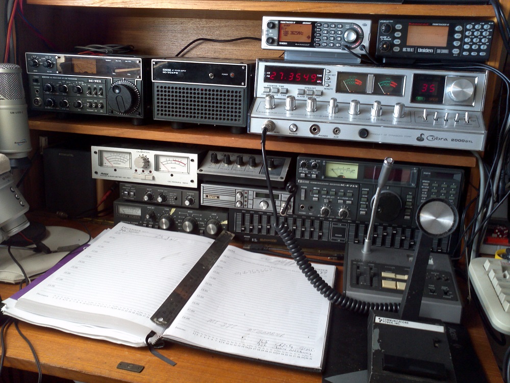
The Cobra 2000 GTL citizen’s band base station radio demonstrates the epitome of contemporary CB base station design. The radio comes equipped with a 2SC1969 RF transistor in the final output stage, a transistor that can produce 25 watts PEP at 12 volts Vcc. This radio is manufactured by Uniden in either Taiwan (to mid 1988) or the Philippines (1988 to final production in 1992). It is well known that these radios can produce 25 watts on single sideband, but on AM they will usually do only 8-10 watts maximum out of the box, even with the carrier set way down to 1-2 watts. This has to do with the design of the radio in AM mode operation.? What we’re going to do here is remove a limitation of the design, and make the radio perform on AM, the way it performs on single sideband. This is really a two-in-one operation, we’re going to perform a negative peak compression (NPC) mod, as well as volting the FINAL.? Don’t get scared away – the tandem modification will ENHANCE audio and not ruin it. It will also keep your neighbors off your back as this is a clean mod. It is important to realize that the ‘volted final’ condition occurs in AM only. In SSB mode, the finals receive full input voltage by design. We will add this capability to AM. Also, you will NOT lose the ability to control carrier power, as VR10 will also continue to be used. VR10 controls the driver, which in turn controls the final. We will not be volting the driver.
My work on this design makes it completely reversible, so that if the desire is to return it to stock, you will be able to do this. I am a stickler for detail, and I don’t like hacking a radio, so I try to do any work as cleanly as possible. As such, the original instructions for the AM volt mod involved cutting the TP7 wire, but I do not like to cut wires so we will add a new ‘terminal’ to attach the existing TP7 wire to, in short – creating a new TP7. The new wire will use both a TP pin and corresponding wire from a non-working donor radio.
Along with the instructions, I will be using pictures to help the viewer perform the mod, because a ‘picture is worth a thousand words’.
The mod limiter will be disabled on the radio. It will not be needed – with the NPC mod, the harmful effects of over modulation will not take place – i.e. harmonics, splatter etc.
1. TR24 or Modulation Limitation
Removing this deactivates the modulation limiters in all modes. Use the front panel mic gain (aka Dynamike) control to set the modulation percentage. Replace the following 10k resistors with 1/4 watt, 4.7k resistors: R126, R124 (both located near the VR3 Squelch range trimpot). If you do not wish to remove TR24, you may add a 1.5k resistor in series with the middle leg of TR24 (the collector). Replace R131 (10k) with a 4.7k resistor (only if you do not remove TR24). My own note: Removing TR26 or R131 will disable the AMC in the AM mode but leave the limiter intact for SSB usage. Since this is a primarily AM mod, and delimiting modulation in SSB is a bad thing for SSB audio clarity, this is the personal route I would take.
| 2. Add a solder bridge, jumper or shunt to the solder side of the board that effectively jumpers out R196. This is a quick way of replacing R196 with a jumper (reducing its value to zero ohms). This increases the range of VR10 (AM dead-key power) so that the dead-key can be set to 1.5 to 2 watts later on. 3. Add a 10 uF 25 or higher volt electrolytic cap to these points: the positive leg goes to the trace that connects to pin 9 of the IC6 (the audio IC), and the negative leg goes to the R194/D63/R228 junction.? This is the mod that compresses the negative modulation peaks and allows the average power to increase based on the modulation percentage (aka the NPC mod). The picture to the right demonstrates the locations on the backside of the PC board showing the physical locations for the parts in step 2 and 3 above. |

| The positive lead of the capacitor is soldered to the point directly below the capacitor itself.? The negative lead is soldered to that yellow wire, which extends to the point on the PC board where the R194/D63/R228 junction exists.?You can see the point directly below the capacitor where the shunt is added that extends the range of VR10. |


| 4. Set the driver bias to 50 mA. (Power up the radio, put it in LSB or USB, set the mic gain at minimum, remove the wire from test point 8, insert a milliamp meter in series between the test point (which is positive) and the wire, key the mic, and adjust VR9 until the meter reads 50 mA.) 5. Set the final bias to 100 mA. (Same instructions as in step 4 except the test point is test point 7, and the adjustment is VR8). On some of the newer radios the final bias can’t be set higher than about 50 mA. The reason is that the value of R179 has been increased in order to decrease the effective range of VR8. To solve the problem, replace R179 with a 500 to 1000 ohm resistor. The picture to the left demonstrates the use of the digital multimeter.? The black probe is touching the yellow wire to the final, where the red probe is being held on TP7.? This is the final bias adjustment – the driver is identical except the wire is violet and the test point is TP8. |
6. Now, we are going to make a new test point 7.? We will use the old driver/final power leads as well as the test point pins from the donor radio.

First, we will remove the leads from the radio, and also the pins.? In the first picture on the right, the pin from TP8 has been unsoldered and is in the jaw of the pliers.? It, and its companion wire, are shown in the image on the far right.? We will solder the pin to the wire, as demonstrated in the pictures below.


| Solder the wire as shown.? Place the short part of the pin inside the wire receptacle.? Add just enough solder to allow a permanent connection.? Let it cool a little, then add a piece of heat shrink tubing over the soldered connection as shown in the below left image.? Heat and then it’s ready to go. |


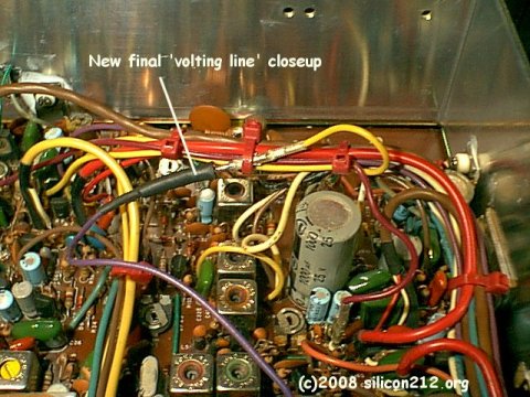
| On the above left image, you can see the heat shrink tube placed over the joint.? Once you have applied heat, the joint should look as it does in the above right picture.? The other end of this wire will be soldered to the +12v source rail on the underside of the PC board.? This rail will have a bunch of open wire positions on it, all in a row.? It is located near the MB3756 voltage regulator switch, as shown in the image on the right.? You may solder this wire to any one of those holes – that doesn’t matter, but do make sure you get the +12v rail!? The rail near it that has a bunch of open connections is neutral (ground) and will result in a radio damaging short circuit if it is soldered here.? Double check your placement with the image. |
Once you are finished with the above steps, you will be at the point of the image on the left.? This is the new TP7.? Remove the yellow wire from TP7 on the PC board and relocate it to this new wire.? Use a zip tie to hold it against the wiring harness where the original TP wires are located.? TP7 on the PC board may be left open (in reality, TP7 and TP8 on the PC board are both electrically connected).
This is the mod that converts the RF final stage to linear in all modes.

7. Power up the radio, put it in the AM mode, key the mic, and set VR10 (AM dead-key power adjustment) for about 1.5 watts.
8. Tune the RF chain coils (L38 and L45 through L48) for maximum peak (modulated) output power in the center of the band (that would be Channel 19 on a stock radio and Channel 40 on one that has the popular expanded frequency range of 26.815 to 28.045).? If you have a favorite channel that is more than 30 channels from 19 or 40, do your tuning on that channel.
9. Double check the dead-key power. It should be around 2 watts.? If it is higher than 2 watts, use VR10 to cut it back to between 1.5 and 2 watts. Don’t overdo it. Keep in mind that the carrier (aka dead-key) power increases up to 10+ watts with modulation, so there’s absolutely no point in having the dead-key power any higher than is required to reliably key an amplifier. Most amps will key reliably with as little as 1/2 watt of dead-key power.
The following numbers are what you should expect. However, since there is a lot of variation in CB test equipment setups, don’t be alarmed if you don’t see these exact numbers. These numbers are provided as a guideline to make sure you did the mods properly.
The dead-key wattage should be 1.5 to 2 watts. The maximum average power should be 10 to 12 watts. And the maximum peak power should be around 25 watts.
10.? Squish, Hammer, Nail, Mallet, Maul!
This page is for informational/educational use only.? (c) 2008, 2009 gary at silicon two one two dot org
This page, and all graphics contained herein are copyright 2001-2008, ‘silicon212’. If you want to use an image, please download and place onto your server. Also, you must leave any identifying marks in the image. THANKS GARY from Greg!
cobra_2000gtl_service-manual-free-download
Or below if above link broken.
http://www.cbtricks.com/radios/cobra/2000gtl/graphics/cobra_2000gtl_sm.pdf